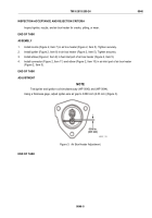
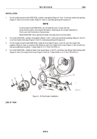
TM-9-2815-205-24 - Page 306 of 856
REMOVAL
1.
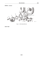
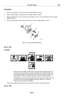
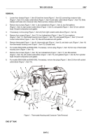
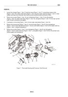
Loosen four clamps (Figure 1, Item 20) and two hoses (Figure 1, Item 22) connecting crossover tube
(Figure 1, Item 21) to water outlet elbow (Figure 1, Item 4) and water outlet elbow (Figure 1, Item 19). Slide
clamps and hoses onto crossover tube. Remove tube, clamps, and hoses.
2.
Remove two screws (Figure 1, Item 1), two lockwashers (Figure 1, Item 2), two flat washers
(Figure 1, Item 3), right coolant outlet elbow (Figure 1, Item 4), and gasket (Figure 1, Item 5) from cylinder
head. Discard lockwashers and gasket.
3.
If necessary, remove plug (Figure 1, Item 24) from right coolant outlet elbow (Figure 1, Item 4).
4.
Remove four screws (Figure 1, Item 13), four lockwashers (Figure 1, Item 12), four washers
(Figure 1, Item 11), thermostat housing cover (Figure 1, Item 15), and gasket (Figure 1, Item 7) from left
coolant outlet elbow (Figure 1, Item 19). Discard lockwashers and gasket.
5.
Remove thermostat (Figure 1, Item 8), thermostat seal (Figure 1, Item 9), and drain cock (Figure 1, Item 14)
from thermostat housing cover (Figure 1, Item 15). Discard seal.
6.
For models 5063-5299 and 5063-5392, if necessary, remove plug (Figure 1, Item 10) from top of thermostat
housing cover (Figure 1, Item 15).
7.
Remove two screws (Figure 1, Item 18), two lockwashers (Figure 1, Item 17), two flat washers
(Figure 1, Item 16), left coolant outlet elbow (Figure 1, Item 19), and gasket (Figure 1, Item 6) from cylinder
head. Discard lockwashers and gasket.
8.
For models 5063-5299 and 5063-5392, if necessary, remove two plugs (Figure 1, Item 23) from left coolant
outlet elbow (Figure 1, Item 19).
3
4
7
8
9
1
10
11
12
13
14
15
16
17
18
19
20
24
23
21
22
2
6
20
5
MAINT_140
Figure 1.
Thermostat Housing and Crossover Tube Removal.
END OF TASK
TM 9-2815-205-24
0047
0047-2
Back to Top

