TM-9-2815-205-24 - Page 288 of 856
REMOVAL
WARNING
Before testing, remove jewelry such as rings, bracelets, wristwatches, and neck chains that
may catch on equipment or cause electrical shorts. Failure to comply may result in injury or
death to personnel.
1.
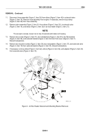
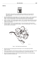
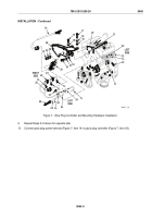
Disconnect glow plug power harness (Figure 1, Item 14) by removing nut (Figure 1, Item 7) and lockwasher
(Figure 1, Item 8) securing red double lead power connection (Figure 1, Item 9) at battery terminal
(Figure 1, Item 6) on solenoid (Figure 1, Item 1). Remove lead and reinstall nut and lockwasher.
2.
Remove nut (Figure 1, Item 10) and lockwasher (Figure 1, Item 11) securing orange switch lead connection
(Figure 1, Item 12) at switch terminal (Figure 1, Item 13) on solenoid (Figure 1, Item 1). Remove lead and
reinstall nut and lockwasher.
3.
Remove nut (Figure 1, Item 5) and lockwasher (Figure 1, Item 4) securing blue or black ground lead
connection (Figure 1, Item 3) to ground terminal (Figure 1, Item 2) on solenoid (Figure 1, Item 1). Remove
lead and reinstall nut and lockwasher.
2
3
4
5
6
7
8
9
10
11
12
14
13
1
MAINT_128
Figure 1.
Glow Plug Power Harness Removal.
4.
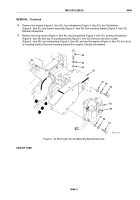
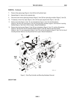
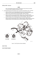
Disconnect and remove glow plug power harness (Figure 2, Item 14) from glow plug controller
(Figure 2, Item 29).
5.
Remove two bolts (Figure 2, Item 23) and two nuts (Figure 2, Item 27) securing two clips (Figure 2, Item 24)
to two brackets (Figure 2, Item 22) on glow plug harness (Figure 2, Item 28) to left cylinder head.
6.
Disconnect three plug ends (Figure 2, Item 25) of glow plug harness (Figure 2, Item 28) at glow plugs
(Figure 2, Item 26) from left cylinder head.
TM 9-2815-205-24
0045
0045-2
Back to Top

