TM-9-2815-205-24 - Page 468 of 856
ASSEMBLY
1.
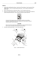
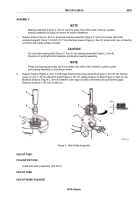
Install new three vanes (Figure 4, Item 14) in rotor of air pump (Figure 4, Item 7).
2.
Install cover (Figure 4, Item 13) and three screws (Figure 4, Item 12) on air pump (Figure 4, Item 7).
Tighten screws.
3.
If removed, install elbow (Figure 4, Item 15) in inlet port and elbow (Figure 4, Item 8) in outlet port of air
pump (Figure 4, Item 7).
4.
Install adapter (Figure 4, Item 9), hose (Figure 4, Item 10), and check valve (Figure 4, Item 11) on outlet
elbow (Figure 4, Item 8).
5.
Place two cushions (Figure 4, Item 5) on bracket (Figure 4, Item 6). Place ignition coil (Figure 4, Item 4)
and air pump (Figure 4, Item 7) on cushions and bracket as shown for the appropriate model.
NOTE
Place clamp (Figure 4, Item 3) with cast part number above ignition coil (Figure 4, Item 4).
6.
Install clamp bracket (Figure 4, Item 3), flat washer (Figure 4, Item 2), and bolt (Figure 4, Item 1) in bracket
(Figure 4, Item 6) over coil (Figure 4, Item 4) and air pump (Figure 4, Item 7). Torque bolt to
60–96 lb-in (7–11 N·m).
TM 9-2815-205-24
0074
0074-6
Back to Top

