TM-9-2815-205-24 - Page 460 of 856
REMOVAL - Continued
7.
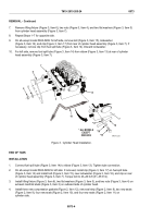
Remove lifting fixture (Figure 3, Item 6), two nuts (Figure 3, Item 4), and two flat washers (Figure 3, Item 5)
from cylinder head assembly (Figure 3, Item 7).
8.
Repeat Steps 1–7 for opposite side.
9.
On all except model 5063-5299: for left side, remove bolt (Figure 3, Item 15), lockwasher
(Figure 3, Item 16), and clip (Figure 3, Item 17) from rear of cylinder head assembly (Figure 3, Item 7). If
necessary, remove clip from fuel spill tube (Figure 3, Item 14). Discard lockwasher.
10.
For left side, remove fuel spill tube (Figure 3, Item 14) from elbow (Figure 3, Item 13) at rear of cylinder
head assembly (Figure 3, Item 7).
5
4
* ALL MODELS
EXCEPT
5063-5299
6
7
7
13
*15
*16
*17
3
14
14
MAINT_202
Figure 3.
Cylinder Head Installation.
END OF TASK
INSTALLATION
1.
Connect fuel spill tube (Figure 3, Item 14) to elbow (Figure 3, Item 13). Tighten tube connection.
2.
On all except model 5063-5299 for left side: if removed, install clip (Figure 3, Item 17) on fuel spill tube
(Figure 3, Item 14) and install bolt (Figure 3, Item 15), new lockwasher (Figure 3, Item 16), and clip on rear
of cylinder head assembly (Figure 3, Item 7). Torque bolt to 23–26 lb-ft (31–35 N·m).
3.
Install lifting fixture (Figure 3, Item 6), two flat washers (Figure 3, Item 5), and two nuts (Figure 3, Item 4) on
exhaust manifold studs (Figure 3, Item 3) on outboard side of cylinder head.
4.
Install three new compression gaskets (Figure 2, Item 12), new seal strip (Figure 2, Item 8), two new seals
(Figure 2, Item 9), four new seals (Figure 2, Item 10), and four new seals (Figure 2, Item 11) on
cylinder side.
TM 9-2815-205-24
0073
0073-4
Back to Top


