TM-9-2815-205-24 - Page 453 of 856
ASSEMBLY - Continued
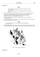
2.
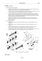
Right injector control tube assembly
a.
Install control lever (Figure 3, Item 11) and left-hand helix yield spring (Figure 3, Item 28) on control
tube (Figure 3, Item 12) with control lever facing front of control tube.
b.
Install two of right-hand helix yield springs (Figure 3, Item 27) and control levers (Figure 3, Item 11) on
control tube (Figure 3, Item 12) with control lever facing front of control tube.
c.
Connect curled end of two yield springs (Figure 3, Item 27) and yield spring (Figure 3, Item 28) to
three rack control levers (Figure 3, Item 11) and roll yield springs into notch or slots in control tube
(Figure 3, Item 12). Turn three adjusting screws (Figure 3, Item 30) with locknuts (Figure 3, Item 29)
far enough into slots to position levers on control tube.
d.
Install return spring (Figure 3, Item 26) and bracket (Figure 3, Item 6) at front of control tube
(Figure 3, Item 12). Connect curled end of return spring to rack control lever and extended end of
spring behind bracket.
3.
Throttle delay assembly
a.
Install joint (Figure 3, Item 19) and new locknut (Figure 3, Item 17) on piston (Figure 3, Item 18).
Tighten nut.
b.
Install link (Figure 3, Item 16) and new locknut (Figure 3, Item 20) on joint (Figure 3, Item 19).
Tighten nut.
c.
If removed, install screw (Figure 3, Item 24) and new locknut (Figure 3, Item 22) on bracket
(Figure 3, Item 21). Tighten nut until width between legs is 1-7/16 inches (36.5 mm).
d.
Install link (Figure 3, Item 16), two screws (Figure 3, Item 23), two bushings (Figure 3, Item 15), and
two new locknuts (Figure 3, Item 14) on bracket (Figure 3, Item 21). Tighten nuts.
1-7/16 in.
(36.5 mm)
LEFT
FRONT SIDE
12
13
17
20
15
14
26
25
16
27
28
29
6
24
30
6
21
22
RIGHT
FRONT
SIDE
THROTTLE DELAY
ASSEMBLY
15
14
13
27
23
26
11
27
28
11
11
27
29
30
29
30
11
11
11
29
30
30
30
29
29
18
19
MAINT_198
Figure 3.
Injector Control Tube Assembly.
END OF TASK
TM 9-2815-205-24
0072
0072-5
Back to Top

