TM-9-2815-205-24 - Page 454 of 856
INSTALLATION
NOTE
Steps 1 and 4 apply to throttle delay assembly used on right side of all except
model 5063-5299.
Legs on lever assembly (Figure 4, Item 9) must face downward and be inboard of
control tube.
1.
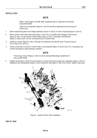
Slide throttle delay piston and linkage assembly (Figure 4, Item 5) in bore of housing (Figure 4, Item 4).
2.
Place injector control tube assembly (Figure 4, Item 10) on cylinder head. Engage control levers
(Figure 4, Item 11) with injector control racks (Figure 4, Item 1) and place end brackets
(Figure 4, Items 6 and 13) over mounting holes in cylinder head.
3.
Install four screws (Figure 4, Item 7) through end brackets into cylinder head. Torque screws to
120–144 lb-in(14–16 N·m).
4.
Check control tube to ensure it moves freely in end brackets (Figure 4, Items 6 and 13). If necessary, tap
control tube lightly to align bearing in brackets.
NOTE
Final torque of nuts (Figure 4, Item 3) is done during throttle delay adjustment of
tune-up (WP 0078).
5.
Install U-bolt (Figure 4, Item 8) around bottom of control tube and through lever assembly (Figure 4, Item 9).
Install two new lockwashers (Figure 4, Item 2) and two nuts (Figure 4, Item 3) on U-bolt. Tighten nuts snug.
13
FRONT
3
4
5
6
7
8
1
9
10
11
2
3
2
MAINT_199
Figure 4.
Injector Control Tube Installation.
END OF TASK
TM 9-2815-205-24
0072
0072-6
Back to Top

