TM-9-2815-205-24 - Page 462 of 856
INSTALLATION - Continued
NOTE
Repeat tightening sequence at least once because first bolts tightened tend to lose
significant clamping load during tightening of remaining bolts. Apply a steady pressure for
two or three seconds at prescribed torque to allow bolts to turn while gaskets yield to their
designed thickness.
10.
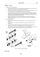
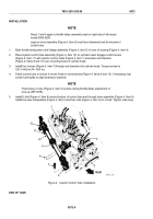
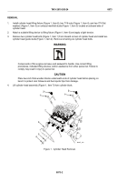
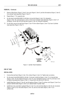
Torque cylinder head bolts (Figure 1, Item 1) to 170–180 lb-ft (231–244 N·m) in 50 lb-ft (68 N·m)
increments. Tighten bolts in alphabetical sequence shown (Figure 4).
11.
Repeat Steps 3–10 for left side.
TOP
E
G
H
F
B
D
A
C
BOTTOM
MAINT_203
Figure 4.
Cylinder Head Torque Sequence.
END OF TASK
FOLLOW ON TASK
1.
Install injector control tubes (WP 0072).
2.
Install fuel rod hoses (WP 0062).
3.
Install throttle control rods (WP 0061).
4.
Install engine rocker arm covers (models 5063-5392, 5063-5393, and 5063-539L) (WP 0053).
5.
Install engine rocker arm covers (model 5063-5299) (WP 0052).
6.
Install fuel lines (models 5063-5393 and 5063-539L) (WP 0051).
7.
Install fuel lines (model 5063-5392) (WP 0050).
8.
Install fuel lines (model 5063-5299) (WP 0049).
9.
Install water outlet elbow and thermostat housing (models 5063-5393 and 5063-539L) (WP 0048).
10.
Install water outlet elbow and thermostat housing (models 5063-5299 and 5063-5392) (WP 0047).
11.
Install exhaust manifolds (WP 0039).
END OF TASK
END OF WORK PACKAGE
TM 9-2815-205-24
0073
0073-6
Back to Top


