TM-9-2815-205-24 - Page 452 of 856
CLEANING
WARNING
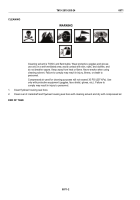
Cleaning solvent is TOXIC and flammable. Wear protective goggles and gloves;
use only in a well-ventilated area; avoid contact with skin, eyes, and clothes; and
do not breathe vapors. Keep away from heat or flame. Never smoke when using
cleaning solvent. Failure to comply may result in injury, illness, or death to
personnel.
Compressed air used for cleaning purposes will not exceed 30 PSI (207 kPa). Use
only with protective equipment (goggles, face shield, gloves, etc.). Failure to
comply may result in injury to personnel.
Wash components with cleaning solvent and dry with compressed air.
END OF TASK
INSPECTION-ACCEPTANCE AND REJECTION CRITERIA
1.
Inspect components for excessive wear, cracks, or damage. Replace if necessary.
2.
Inspect yield springs and return springs for wear and fractures.
END OF TASK
ASSEMBLY
1.
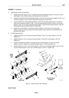
Left injector control tube assembly
a.
Install return spring (Figure 3, Item 26) on control tube (Figure 3, Item 25) and against rear bracket
(Figure 3, Item 13).
b.
Install two of right-hand helix springs (Figure 3, Item 27) and two control levers (Figure 3, Item 11) on
control tube (Figure 3, Item 25) with control levers facing rear of control tube.
c.
Install left-hand helix yield spring (Figure 3, Item 28) and control lever (Figure 3, Item 11) on control
tube (Figure 3, Item 25) with control lever facing rear of control tube.
d.
Connect curled end of two yield springs (Figure 3, Item 27) and yield spring (Figure 3, Item 28) to
three rack control levers (Figure 3, Item 11) and roll yield springs into notch or slots in control tube
(Figure 3, Item 25). Turn three adjusting screws (Figure 3, Item 30) with locknuts (Figure 3, Item 29)
far enough into slots to position levers on control tube.
e.
Connect curled end of control tube return spring (Figure 3, Item 26) to rack control lever
(Figure 3, Item 11) and extended end of spring behind rear bracket (Figure 3, Item 13).
f.
Install bracket (Figure 3, Item 6) to front of control tube (Figure 3, Item 25).
TM 9-2815-205-24
0072
0072-4
Back to Top

