TM-9-2815-205-24 - Page 450 of 856
REMOVAL
NOTE
Steps 1 and 4 apply to throttle delay assembly used on right side of all except
model 5063-5299.
Place wiping rag over oil drain holes to prevent loss of parts.
1.
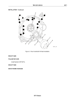
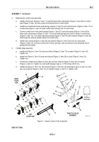
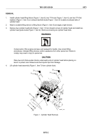
Remove two nuts (Figure 1, Item 3), two lockwashers (Figure 1, Item 2), and U-bolt (Figure 1, Item 8) from
throttle delay lever assembly (Figure 1, Item 9). Discard lockwashers.
2.
Remove four screws (Figure 1, Item 7) fastening injector control tube brackets (Figure 1, Item 6) to
cylinder head.
3.
Disengage control rack levers (Figure 1, Item 11) from injector control racks (Figure 1, Item 1) and lift tube
assembly (Figure 1, Item 10) from cylinder head.
4.
Remove piston and link assembly (Figure 1, Item 5) from throttle delay bracket (Figure 1, Item 4).
FRONT
3
4
5
6
7
8
1
9
10
11
2
3
2
MAINT_196
Figure 1.
Injector Control Tube Removal.
END OF TASK
DISASSEMBLY
NOTE
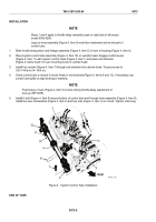
Note shape and location of the yield and return springs during disassembly.
1.
Injector control tube assembly (left or right)
a.
For left control tube assembly, remove bracket (Figure 2, Item 6) from front of tube.
TM 9-2815-205-24
0072
0072-2
Back to Top


