TM-9-2815-205-24 - Page 97 of 856
INSTALLATION - Continued
CAUTION
Nonmetallic seal must set in groove, or inside screw hole bosses of lower flange, to
prevent damage. If seal is not in position, container assembly can damage seal and seal
will fail.
NOTE
Container (NSN 8145-00-138-7809) for model 5063-5299 uses 20 screws, no flat
washers, and 20 nuts. Torque screws to 54–59 lb-ft (73–80 N·m).
Container (NSN 2815-01-232-9447) uses 24 screws, 24 flat washers, and 24 nuts.
Torque screws to 31–37 lb-ft (42–50 N·m).
3.
Using two adjustable 2-point slings (Figure 1, Item 2), install upper container half (Figure 1, Item 3), screws
(Figure 1, Item 6), flat washers (Figure 1, Item 5), and nuts (Figure 1, Item 4) on lower container half
(Figure 1, Item 7). Tighten screws (Figure 1, Item 6) progressively around perimeter of container. Torque
screws (Figure 1, Item 6) to values noted above.
4.
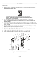
Allow container to stand for a minimum of 12 hours. Then check humidity indicator (Figure 3, Item 11) and
verify that air pressure is maintained.
NOTE
Under moisture-free conditions, the humidity indicator will show blue in color. Pink
indicates excessive moisture in container.
5.
If humidity indicator (Figure 3, Item 11) is pink, remove upper container half (Figure 3, Item 3), replace all
desiccant bags, and replace container nonmetallic seal (Figure 2, Item 9). Install upper container half
(Figure 3, Item 3) and test container as indicated in Steps 3–5.
3
11
MAINT_017
Figure 3.
Upper Container Half.
END OF TASK
END OF WORK PACKAGE
TM 9-2815-205-24
0010
0010-5/blank
Back to Top


