TM-9-2815-205-24 - Page 105 of 856
ASSEMBLY
NOTE
Water outlet housing is installed on oil cooler end opposite oil drain plug with
housing reservoir directly above oil inlet port.
Two long bolts (Figure 6, Item 29) are installed in holes 90 degrees
counterclockwise from oil inlet port.
1.
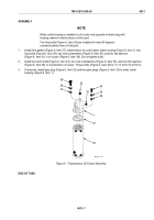
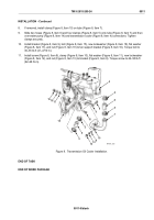
Install new gasket (Figure 6, Item 37), transmission oil cooler water outlet housing (Figure 6, Item 1), two
long bolts (Figure 6, Item 29), two new lockwashers (Figure 6, Item 30), and two flat washers
(Figure 6, Item 31) in oil cooler (Figure 6, Item 38). Do not tighten bolts.
2.
Install four short bolts (Figure 6, Item 34), four new lockwashers (Figure 6, Item 35), and four flat washers
(Figure 6, Item 36), in transmission oil cooler. Torque bolts (Figure 6, Item 34) to 13–17 lb-ft (18–23 N·m).
3.
If removed, install pipe plug (Figure 6, Item 32) and two pipe plugs (Figure 6, Item 33) in water outlet
housing (Figure 6, Item 1).
1
31
30
29
32
33
36
35
34
37
38
MAINT_023
Figure 6.
Transmission Oil Cooler Assembly.
END OF TASK
TM 9-2815-205-24
0011
0011-7
Back to Top


