TM-9-2815-205-24 - Page 107 of 856
INSTALLATION - Continued
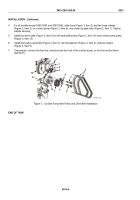
8.
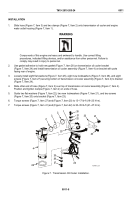
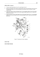
If removed, install clamp (Figure 8, Item 10) on tube (Figure 8, Item 7).
9.
Slide two hoses (Figure 8, Item 6) and four clamps (Figure 8, Item 5) onto tube (Figure 8, Item 7) and then
over water pump (Figure 8, Item 14) and transmission cooler (Figure 8, Item 4) connections. Tighten
clamps securely.
10.
Install bracket (Figure 8, Item 9), bolt (Figure 8, Item 15), new lockwasher (Figure 8, Item 18), flat washer
(Figure 8, Item 17), and nut (Figure 8, Item 19) to fan support bracket (Figure 8, Item 16). Torque bolt to
30–35 lb-ft (41–47 N·m).
11.
Install screw (Figure 8, Item 8), clamp (Figure 8, Item 10), flat washer (Figure 8, Item 11), new lockwasher
(Figure 8, Item 12), and nut (Figure 8, Item 13) to bracket (Figure 8, Item 9). Torque screw to 46–50 lb-ft
(62–68 N·m).
4
5
6
5
7
9
10
11
8
12
13
14
15
16
19
17
18
5
5
6
MAINT_025
Figure 8.
Transmission Oil Cooler Installation.
END OF TASK
END OF WORK PACKAGE
TM 9-2815-205-24
0011
0011-9/blank
Back to Top


