TM-9-2815-205-24 - Page 111 of 856
REMOVAL - Continued
*2
3
4
8
10
12
11
13
9
14
15
**14
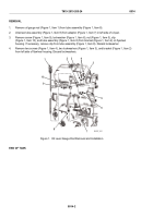
MODELS
*5063-5393
**5063-539L
MAINT_026A
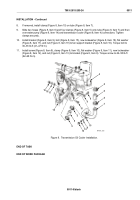
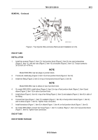
Figure 2.
Fuel Injection Box and Lines Removal and Installation (2 of 2).
END OF TASK
INSTALLATION
1.
Install two screws (Figure 2, Item 13), fuel junction block (Figure 2, Item 9), two new lockwashers
(Figure 2, Item 11), and two nuts (Figure 2, Item 10) on bracket (Figure 2, Item 12). Torque screws to
30–35 lb-ft (41–47 N·m).
NOTE
Model 5063-539L has two plugs in junction block.
2.
If removed, install plug (Figure 2, Item 14) in fuel junction block (Figure 2, Item 9).
3.
Install tee fitting (Figure 2, Item 3) in top of fuel junction block (Figure 2, Item 9).
NOTE
Model 5063-539L has no elbow on top of junction block.
4.
On model 5063-5393, install elbow (Figure 2, Item 2) in top of fuel junction block (Figure 2, Item 9) and
elbow (Figure 2, Item 15) in side of junction block.
5.
Install elbow (Figure 2, Item 4) in top of tee fitting (Figure 2, Item 3) and adaptor (Figure 2, Item 8) in side of
tee fitting.
6.
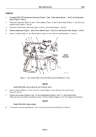
Connect fuel hose (Figure 1, Item 7) to adaptor (Figure 1, Item 8) on fuel junction block (Figure 1, Item 9)
and to elbow (Figure 1, Item 6). Tighten hose connection.
7.
Install transducer (Figure 1, Item 5) in elbow (Figure 1, Item 4) on fuel junction block (Figure 1, Item 9).
8.
On model 5063-5393, connect fuel hose (Figure 1, Item 1) to elbow (Figure 1, Item 2) in fuel junction block
(Figure 1, Item 9). Tighten hose connection.
END OF TASK
END OF WORK PACKAGE
TM 9-2815-205-24
0012
0012-3/blank
Back to Top


