TM-9-2815-205-24 - Page 117 of 856
ADJUSTMENT
1.
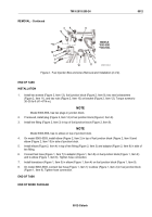
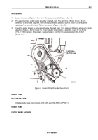
Loosen two screws (Figure 4, Item 5) on idler pulley assembly (Figure 4, Item 7).
2.
Pry upward on tang of idler pulley assembly (Figure 4, Item 7) to get 1/4 to 3/8 inch (6.4 to 9.5 mm)
deflection on drive belts (Figure 4, Item 6) midway between pulleys (Figure 4, Items 15 and 16) while
applying a firm push with thumb. Tighten two screws (Figure 4, Item 5).
3.
Check for proper tension by using straight edge (Figure 4, Item 17) to measure deflection across drive belts
at pulleys (Figure 4, Items 15 and 16). If dial indicator tensionmeter is available, check for 40–50 lbs
(173–217 N·m) tension. If necessary, readjust tension, and then torque two screws to 30–35 lb-ft
(41–47 N·m).
5
17
15
16
6
7
1/4 TO 3/8 in.
(6.4 TO 9.5 mm)
MAINT_030
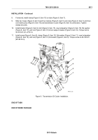
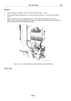
Figure 4.
Coolant Pump Drive Belt Adjustment.
END OF TASK
FOLLOW ON TASK
Install water by-pass hose (models 5063-5393 and 5063-539L) (WP 0011).
END OF TASK
END OF WORK PACKAGE
TM 9-2815-205-24
0013
0013-5/blank
Back to Top

