TM-9-2815-205-24 - Page 102 of 856
DISASSEMBLY
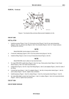
1.
Remove two long bolts (Figure 3, Item 29), two lockwashers (Figure 3, Item 30), and two flat washers
(Figure 3, Item 31) from water outlet housing (Figure 3, Item 1). Discard lockwashers.
2.
Remove four short bolts (Figure 3, Item 34), four lockwashers (Figure 3, Item 35), four flat washers
(Figure 3, Item 36), water outlet housing (Figure 3, Item 1), and gasket (Figure 3, Item 37) from top of oil
cooler (Figure 3, Item 38). Discard gasket and lockwashers.
3.
If necessary, remove pipe plug (Figure 3, Item 32) and two pipe plugs (Figure 3, Item 33) from transmission
oil cooler water outlet housing (Figure 3, Item 1).
1
31
30
29
32
33
36
35
34
37
38
MAINT_020
Figure 3.
Transmission Oil Cooler Disassembly.
END OF TASK
CLEANING
1.
Position oil cooler (Figure 4, Item 38) in a vertical position. Ensure oil cooler is adequately supported for
cleaning operation.
CAUTION
Do not use 1-1/4 NPT reducer bushing. Oil cooler port is not tapered and damage
will result.
2.
Install fabricated machine-threaded plug (Figure 4, Item 39) from oil coolers pressure testing kit in bottom
port of oil cooler (Figure 4, Item 38).
3.
Connect air line to fabricated machine-threaded plug (Figure 4, Item 39).
TM 9-2815-205-24
0011
0011-4
Back to Top


