TM-9-2815-210-34-2-1 - Page 177 of 259
Section III.
DISASSEMBLY OF
NOTE
TM 9-2815-210-34-2-1
ENGINE ASSEMBLY
This procedure is the same for all engine models
except where noted.
TOOLS:
Engine transport stand, NSN 4910-00-338-6673
Engine maintenance stand, NSN 4910-00-529-8387
Puller, NSN 5120-00-134-7463
Puller kit, pn 8708724
Plug, pn 10899178
Wood block, 2x4x18 inches (2)
Brass rod
SUPPLIES
:
Lacquer, nitrocellulose, type I, TT-L-50
Tool tags
Wire
Steel bar stock
Bolt (2)
Tag s
PERSONNEL
: T
W O
EQUIPMENT CONDITION:
Engine mounted on transport stand.
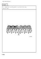
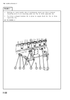
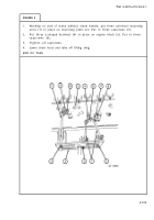
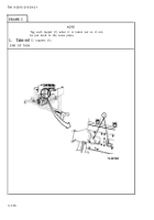
3-31. MOUNTING ENGINE ON MAINTENANCE STAND.
a.
Preliminary y Procedures.
(1) Remove engine from shipping container and place on transport stand.
Refer to para 2-3 through para 2-5.
(2) Remove generator and mounting bracket. Refer to para 3-4.
(3) Remove crankcase breather adapter. Refer to para 3-19.
(4) If engine is equipped with a turbocharger, remove turbocharger. Refer
to para 3-5.
(5) Remove oil pressure regulator valve. Refer to para 3-24.
(6) Remove air compressor and mounting bracket. Refer to para 3-12 and
3-17.
(7) Remove fuel filter and mounting bracket. Refer to para 3-14.
(8) If engine is equipped with hydraulic pump, remove hydraulic pump.
Refer to para 3-13.
(9) Remove fuel injector pump and fuel injector lines. Refer to para 3-10
and 3-8.
(10) Remove oil filter and mounting bracket. Refer to para 3-11 and 3-15.
(11) Remove oil cooler and oil cooler water hose. Refer to para 3-15.
(12) Remove tappet chamber covers. Refer to para 3-16.
(13) Remove intake and exhaust manifolds. Refer to para 3-30.
3-129
Back to Top


