TM-9-2815-225-34-P - Page 412 of 736
TM 9-2815-225-34&P
0045 00
0045 00-8
ENGINE ACCESSORIES INSTALLATION (Contd)
VIBRATION DAMPER AND CRANKSHAFT PULLEY
CAUTION
To avoid engine damage, ensure mounting surfaces of vibration
damper and crankshaft pulley are clean and dry. Do not get
any lubricating oil on these surfaces.
1.
Install two vibration damper guide pins (5) on two opposite holes in face of crankshaft (6).
2.
Install crankshaft pulley (4) and vibration damper (3) on two guide pins (5) and push into
crankshaft (6) until seated.
3.
Apply a coat of clean lubricating oil to threads of six screws (1) and washers (2).
4.
Install four screws (1) and washers (2) on vibration damper (3), crankshaft pulley (4), and
crankshaft (6).
5.
Install remaining two screws (1) and washers (2) on vibration damper (3), crankshaft pulley (4),
and crankshaft (6). Tighten screws 190 lb-ft (258 N
•
m).
NOTE
Total indicator reading must not exceed 0.004 in. (0.102 mm)
per 1.0 in. (25.4 mm) of vibration damper diameter. Remove
and discard vibration damper if not within limits.
6.
Using dial indicator gauge, measure movement on vibration damper (3) circumference by rotating
crankshaft (6).
NOTE
Crankshaft must be kept at front or rear limit of thrust
clearance while measuring movement of vibration damper face.
Total indicator reading must not exceed 0.007 in. (0.178 mm)
per 1.0 in. (25.4 mm) of the vibration damper radius. Remove
and discard vibration damper if not within limits.
7.
Using dial indicator gauge, measure movement of vibration damper (3) face by rotating
crankshaft (6).
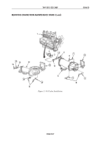
Figure 4. Vibration Damper and Crankshaft Pulley Installation.
1
2
3
4
5
6
END OF WORK PACKAGE
Back to Top


