TM-9-2910-226-34 - Page 56 of 208
TM 9-2910-226-34
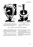
Figure 3-25. Removing quill shaft pad cover.
b.
Refer to figure 3-26. Cut locking wire (A) and
remove machine screw (B) and copper gasket (C).
Discard copper gasket. Remove quill shaft assembly
(D).
Figure 3-26. Removing quill shaft assembly.
3-16. Removal of Camshaft.
a.
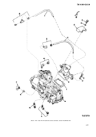
Refer to figure 3-27.
Straighten tabs on lockwashers (A) and remove four
machine screws and lockwashers (B). Remove
bearing retaining plate (C). Remove pump housing
from holding fixture.
3-10
Back to Top

