TM-9-2910-226-34 - Page 51 of 208
TM 9-2910-226-34
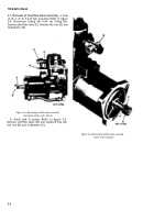
(2) Refer to figure 3-11. Remove two capscrews
(A), lockwashers (B), and flat washers (C). Remove
stop plate and bridge assembly (D).
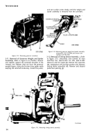
(3) Refer to figure 3-12. Remove nut (A), lock-
washer (B), stop plate bridge (C), lockwasher (D)
and nut (E) from stop plate.
Figure 3-11. Removing stop plate and bridge assembly
(code G pumps).
Figure 3-12. Disassembling stop plate and bridge assembly (code G pumps).
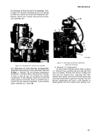
3-10. Removal of Governor.
Refer to figure 3-13. Cut
lockwashers (E). Remove governor housing and
locking wire (A) and remove three capscrews (B),
associated parts (F). Remove and discard governor
lockwashers (C), and two machine screws (D) and
housing gasket (G).
3-5
Back to Top

