TM-9-2910-226-34 - Page 52 of 208
TM 9-2910-226-34
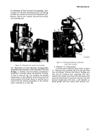
and turn puller screw slowly until the weight and
spider assembly is removed from the camshaft.
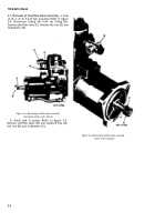
Figure 3-13. Removing governor assembly.
3-11. Removal of Governor Weight and Spider
Assembly.
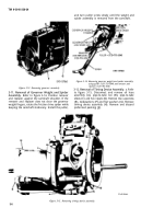
Refer to figure 3-14. Position remover
and replacer against the camshaft shoulder. If the
remover and replacer does not clear the governor
weight fingers, rotate the friction drive spider while
keeping the camshaft stationary. Install the puller,
Figure 3-14. Removing governor weight and spider assembly
using puller 5120-793-5048 and remover and
replacer 5120-793-5055.
3-12. Removal of Timing Device Assembly.
a.
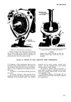
Refer
to figure 3-15. Disconnect and remove oil hose
assembly (A), pipe-to-tube tee (B), pipe-to-tube
elbow (C) and hex nipple (D). Remove two capscrews
(E), Iockwashers (F) and flat washers (G). Remove
timing device assembly (H). Remove and discard
preformed packing (J).
Figure 3-15. Removing timing device assembly.
3-6
Back to Top

