TM-9-2910-226-34 - Page 80 of 208
TM 9-2910-226-34
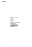
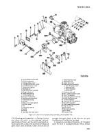
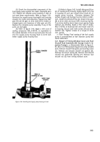
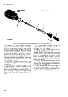
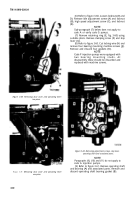
Figure 3-45. Disassembling or assembling timing window cover and fuel shutoff rod assembly.
b. Inspection and Repair.
Inspect and repair
timing window cover and fuel shutoff rod assembly
as follows. Check condition of the rod return spring
(E, fig. 3-45) and replace the spring when it does not
pass visual inspection. Examine the timing window
cover for cracks or distortion. Replace the cover
when cracked or distorted. Examine the gasket
surface of the cover for scratches, nicks, or burs.
Repair minor damage with crocus cloth or a fine mill
file and replace when it is not repairable. Inspect rod
(G) and bearing screw (C) for evidence of wear. Rod
must move freely in screw.
c. Assembly.
Assemble the fuel shutoff rod
assembly and timing window cover as follows. Refer
to figure 3-45.
(1) Install shutoff rod preformed packing (F),
rod return spring (E), and bearing screw (C) on fuel
shutoff rod (G). Compress rod return spring and
position shutoff fitting (B) on fuel shutoff rod and
aline holes in rod and fittings. Drive fitting retaining
pin (A) through holes. Stake fitting retaining pin in
place.
(2) Position shutoff rod gasket (D) on fuel
shutoff rod assembly and install shutoff re
assembly in timing window cover.
3-22. Repair of Fuel Shutoff Solenoid Cover
Assembly (Code A Injection Pumps).
a.
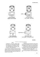
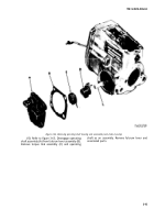
Refer to figure 3-46. Apply 24 v dc to solenoid
electrical connection (A) and ground to housing (F)
to check for solenoid plunger movement. If plunger
(G) does not actuate, replace complete fuel shutoff
solenoid cover assembly. If it does operate, complete
inspection as follows.
b.
Examine the timing window housing portion
(F) for cracks or distortion, and mating surface for
scratches, nicks, or burs. Repair minor damage with
crocus cloth or a fine mill file.
c.
Inspect blackout stop shell (B) for wear or
damage. If worn or damaged, remove sleeve (E), nut
(D), washer (C) and shell (B). Install new shell,
washer, nut, sleeve and repeat step
a
above.
3-34
Back to Top

