TM-9-2910-226-34 - Page 84 of 208
TM 9-2910-226-34
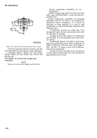
Figure 3-52. Inspecting
fuel
density compensator brass plug
for leakage.
(5)
Check compensator for fuel leakage around
the piston shaft and at the brass plug under the stop
plate guide (fig. 4-52). A trace of fuel i
S
permissible)
but if a drop forms, replace the compensator.
(6) If compensator operation meets this test, no
further inspection is necessary.
(7) If compensator operation does not meet this
test, replace with a new unit.
c.
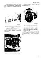
If compensator 2910-907-0665 is equipped with
an undrilled link and a push nut in place of drilled
link (A), washer (B) and pin (C) fig. 3-53, discard nut
and modify link as shown in figure 3-53, by drilling a
hole and using the desired washer and pin.
Figure 3-53. Modification of fuel density compensator fuel
control link.
3-25. Repair
of Governor
Assembly.
a.
Disassembly.
Disassemble the governor assembly as
follows:
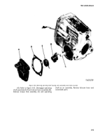
(1) Refer to figure 3-54. Cut locking wire (A) and
remove two capscrews (B) and lockwashers (C).
Remove governor end cap (D). Remove and discard
cap gasket (E).
Figure 3-54. Removing governor end cap.
3-38
Back to Top


