TM-9-2910-226-34 - Page 85 of 208
TM 9-2910-226-34
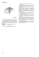
(2) Refer to figure 3-55. Remove outer spring
spacer (A), inner spring spacer (B), governor outer
spring (C), governor inner spring (D), and pipe plug
(E).
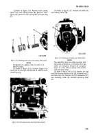
(4) Refer to figure 3-57. Remove oil baffle (A)
and sliding sleeve (B).
Figure 3-55. Removing inner and outer springs and spacers.
NOTE
Paragraph (3) applies only to code A in-
jection pumps.
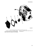
(3) Refer to figure 3-56. Unhook torque link
spring (A) from torque link (B) and oil baffle (C) and
remove spring.
Figure 3-57. Removing oil baffle and sliding sleeve.
NOTE
The operating lever on code A pumps and
early code G pumps is a one-piece lever; all
others are two-piece. Discard all one-piece
levers on early code G pumps and replace
with two-piece lever.
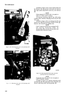
(5) Refer to figure 3-58 or 3-59. Remove the lead
seal (A). Remove machine bolts (B), lockwashers (C)
and dust cover (D). Remove nut (E), lockwasher (F),
and clamping screw (G). Remove operating lever
(H).
Figure 3-56. Removing torque link spring (Code A pumps).
3-39
Back to Top

