MWO-5-2350-262-35-3 - Page 9 of 45
MWO 5-2350-262-35-3
2-3
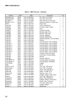
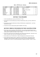
Table 2-1.
MWO Parts List – Continued.
Part No.
CAGE
NSN
Description
Qty
8-4 TRTX-S
30780
Reducer, Tube, -8/-4
1
8338561
19207
Shell
2
8338562
19207
Insulator, Bushing, Sleeve
2
8338564
19207
Terminal
2
900729-3
01276
Clamp, Loop
6
MS21333-104
80502
Clamp, Loop
3
MS3367-1-0
96906
6” Cable Ties
3
12502193
19207
Chain Giude
2
SECTION II
TOOLS REQUIRED
1.
Tool Kit, General Mechanics: Automotive, NSN 5180-00-177-7033.
2.
Shop Equipment, Automotive Maintenance and Repair: Field Maintenance, Basic, Less Power, NSN 4910-00-
754-0705.
3.
Shop Equipment, Automotive Maintenance and Repair: Field Maintenance, Supplemental No.1, Less Power,
NSN 4910-00-754-0706.
4.
Lifting device must have a weight capacity greater than 3865 lb (1753.135 kg).
SECTION III
REMOVAL PROCEDURES FOR TRACK ADJUSTING SYSTEM
1.
Remove apron and dozer assembly per TM 5-2350-262-20-1, Apron and Dozer Assembly Replacement and
Repair.
Remove and inspect steel dozer blade from assembly and if serviceable, retain for future use.
Set aside
remaining parts for disposition per Chapter 1, Section 1-8, step c.
2.
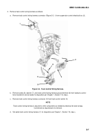
Remove apron wiring harness per TM 5-2350-262-34, Apron Wiring Harness Replacement.
Inspect apron wiring
harness, nut, washer, screw, and pin and if serviceable, retain for future use.
3.
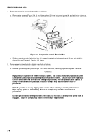
Remove battery box per TM 5-2350-262-20-1, Battery Box Replacement and retain parts for future use.
4.
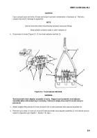
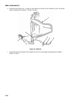
Remove grease track adjusting cylinders, if applicable, per TM 5-2350-262-20-2, Track Adjusting Cylinder
Replacement.
Retain and inspect pin, washers, screw, and locknut from final drive adjusting flange and if
serviceable, retain for future use.
Set aside remaining parts for disposition per Chapter 1, Section 1-8, step c.
Back to Top

