MWO-5-2350-262-35-4 - Page 86 of 207
MWO 5--2350--262--35--4
3--57
SECTION III MODIFICATION OF MAIN HYDRAULIC FILTER AREA
-- CONTINUED
3--10 MODIFICATIONS TO MAIN PUMP RIGHT HYDRAULIC FILTER AREA – INCLUDING
ADDITION OF BALL VALVE V21 AND PRESSURE TRANSDUCER T3 --
CONTINUED
NOTE
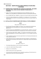
Steps k through ab below apply to Figure 3--37.
k.
Install adapter, 8F650X--SS, (2) and o--ring, MS28778--8, (3) on hydraulic filter head (4).
l.
Install swivel nut tee, MS51523B8, (31) on adapter (2) mounted on hydraulic filter head (4).
m. Install another adapter, 8F650X--SS, (30) and o--ring, MS28778--8, (29) on top of manual ball valve,
BVHP--08--SSS--1NG, (28).
n.
Install manual ball valve (28) on lower end of swivel nut tee (31).
o.
Install bulkhead adapter, 8WF50X--SS, (27) and o--ring, MS28778--8, (26) in bottom of manual ball valve
(28).
p.
Place two flat washers, 10910174--8, (25) loosely on bulkhead adapter (27).
q.
Thread jam nut, MS51860--56Z, (24) loosely onto end of bulkhead adapter (27) to hold two flat washers
(25) in position. Do not tighten jam nut at this time.
r.
Install swivel adapter, 8F650X--SS, (8) and o--ring, MS28778--8, (9) on top of pressure relief valve (21).
Back to Top


