MWO-5-2350-262-35-4 - Page 93 of 207
MWO 5--2350--262--35--4
3--64
SECTION III MODIFICATION OF MAIN HYDRAULIC FILTER AREA
-- CONTINUED
3--11 MODIFICATIONS TO MAIN PUMP LEFT HYDRAULIC FILTER AREA – INCLUDING
ADDITION OF BALL VALVE V22 AND PRESSURE TRANSDUCERS T4 --
CONTINUED
w.
Install correct (previously removed) male/female quick--disconnect (QD) fitting (14) and o--ring,
MS28778--4, (15), noting difference in male/female QD connections for left and right filter assemblies.
x.
Place “V22 MAIN PUMP” label, 12496928--2, on flat portion (to the right of handle) of ball valve V22 (28).
y.
Connect new hydraulic relief bypass hose, 13214E2501--12, (7) between port T 13L of new pressure
relief valve (21) and union elbow (1) (connected through swivel nut tee (31)) connected to inlet port 13L
of filter manifold.
3--12 INSTALLATION OF MODIFIED MAIN PUMP HYDRAULIC FILTER ASSEMBLIES
NOTE
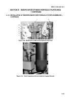
Steps a through j apply to Figure 3--40.
a.
Reinstall hydraulic filter guard, 12379480, in new location in bowl compartment front bulkhead using
three new locking screws, B1821BH038C100L, and three previously removed flat washers
(MS27183--14).
b.
Using three locking screws, B1821BH038C150L, (4) and three flat washers, 10910174--3, (5) for each
plate (6), install left and right hydraulic filter mounting plates (6) on bowl compartment front bulkhead.
c.
Install one ball valve support bracket, 12496967, (1) on each filter mounting plate (6) with two locking
screws, B1821BH038C100L, (2) and two flat washers, MS27183--14, (3). Do not tighten screws at this
time.
d.
Position modified filter assembly over ball valve support bracket (1) with bracket positioned between two
loosely installed flat washers (3).
e.
Install modified left (8) and right (7) hydraulic high--pressure filter assemblies on mounting plates (6) in
main filter portion of bowl area per TM 5--2350--262--20--2, Hydraulic High--Pressure Filter and Element
Replacement.
NOTE
Step f applies to Figure 3--41.
f.
Push hydraulic fittings fully back, into the mounting slot in support bracket.
g.
Loosen and re--tighten hydraulic fittings as required.
h.
Tighten jam nut on bulkhead fitting.
i.
Tighten mounting screws to secure support bracket.
j.
Connect previously removed hydraulic hoses to modified filter assemblies per TM 5--2350--262--20--2,
Hydraulic High--Pressure Filter and Element Replacement.
Back to Top


