MWO-5-2350-262-35-4 - Page 79 of 207
MWO 5--2350--262--35--4
3--50
SECTION II INSTALLATION OF HDC PRIMARY MANIFOLD ASSEMBLY,
MANUAL SHUT–OFF VALVE V23, AND LEFT MAIN MANIFOLD PRESSURE
TRANSDUCER T7 -- CONTINUED
3--8
CONNECTION OF OTHER HYDRAULIC COMPONENTS TO HDC PRIMARY
MANIFOLD ASSEMBLY AND DCV BANK -- CONTINUED
NOTE
It may be necessary to re--orient some components (that are not modified as part of the
HDC installation) to provide good hydraulic connections.
NOTE
Steps q through aa apply to Figure 3--32.
q.
Install new hydraulic hose, 13214E2457--19, (2) between port 9 of primary manifold assembly and rear
tee on port 9 of left main manifold (rear side). It may be necessary to orient tee connector to approximate
five o--clock position (120
_
) for proper connection.
r.
Retag and install hydraulic hose, 13214E2457--20 (changed from 13214E2457--4) (not visible in
Figure 3--32) between port 9A on back (only port on back) of primary manifold assembly and port 9 of
main accumulator.
s.
Retag and install hydraulic hose, 13214E2457--21 (changed from 13214E2457--9), (9) between port 17R
(bottom) of primary manifold assembly and port 17R of left main manifold (top side).
NOTE
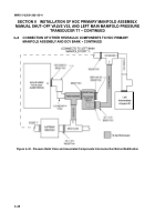
Figure 3--33 shows the orientation of the hoses and fittings connected to the circuit 19
and circuit 20 tees behind the left main manifold. The upper portion of Figure 3--33
shows the components before the modification while the lower portion of the figure shows
the components after the modification.
NOTE
Steps t and u below also apply to Figure 3--33.
t.
Retag and install hydraulic hose, 13214E2457--22 (changed from 13214E2457--10), (4) between port 19
(bottom) of primary manifold assembly and circuit 19 tee (forward). It may be necessary to re--orient the
circuit 19 tee parallel to the bottom of the bowl as shown on lower portion of Figure 3--33 to ensure
proper connection.
u.
Re--orient circuit 20 tee (rear) such that hydraulic hose from DCV bank control valve 20 (VLV 20) is
oriented at approximately a 45
_
angle from horizontal as shown in lower portion of Figure 3--33. This
allows more flexibility in routing and movement of other hydraulic hoses.
v.
Retag and install hydraulic hose, 13214E2457--23 (changed from 13214E2457--11), (5) between port 17L
(bottom) of primary manifold assembly and port 17L of left main manifold (top side).
Back to Top


