MWO-5-2350-262-35-4 - Page 76 of 207
MWO 5--2350--262--35--4
3--47
SECTION II INSTALLATION OF HDC PRIMARY MANIFOLD ASSEMBLY,
MANUAL SHUT–OFF VALVE V23, AND LEFT MAIN MANIFOLD PRESSURE
TRANSDUCER T7 -- CONTINUED
3--8
CONNECTION OF OTHER HYDRAULIC COMPONENTS TO HDC PRIMARY
MANIFOLD ASSEMBLY AND DCV BANK -- CONTINUED
NOTE
Steps m through o below apply to Figure 3--30.
NOTE
Pressure relief valve is being relocated and pressure setting will have to be readjusted.
Plug on relief valve should not be removed until it is determined if it is required for
pressure adjustment.
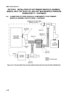
m. Disconnect and remove pressure relief valve 1A32--FBT--60SV917 (and other items shown shaded) from
lower bowl area (behind left main manifold). Refer to TM 5--2350--262--20--2. Figure 3--30 is an
interconnection diagram of the pressure relief valve and associated components before modification.
Retain the pressure relief valve; it will be relocated to hydraulic filter area.
n.
Remove and discard three o--rings, MS28778--8, from pressure relief valve.
o.
Remove and discard metal tube assembly 12332101, tube--to--boss tee MS51530A8S, and o--ring
MS28778--8. Remove and discard metal tube assembly 13214E2842, if not previously removed in step
m.
Back to Top


