MWO-5-2350-262-35-4 - Page 74 of 207
MWO 5--2350--262--35--4
3--45
SECTION II INSTALLATION OF HDC PRIMARY MANIFOLD ASSEMBLY,
MANUAL SHUT–OFF VALVE V23, AND LEFT MAIN MANIFOLD PRESSURE
TRANSDUCER T7 -- CONTINUED
3--8
CONNECTION OF OTHER HYDRAULIC COMPONENTS TO HDC PRIMARY
MANIFOLD ASSEMBLY AND DCV BANK -- CONTINUED
NOTE
Step e below applies to Figure 3--28.
e.
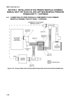
Install new hydraulic hose, 13214E2457--18, (2) between port 7 of primary manifold assembly and tee on
port 7 of left main manifold (rear side). It may be necessary to orient tee to approximate three o--clock
position (90
_
). Item (1) identifies new hydraulic hose, 13214E2457--19.
NOTE
It may be necessary to remove other hydraulic hoses connected to left main manifold to
facilitate modification. All hydraulic hoses that need to be removed should be identified
and tagged for later reconnection.
Figure 3--28. Installation of Hydraulic Hose 13214E2457--18
Back to Top


