MWO-5-2350-262-35-4 - Page 75 of 207
MWO 5--2350--262--35--4
3--46
SECTION II INSTALLATION OF HDC PRIMARY MANIFOLD ASSEMBLY,
MANUAL SHUT–OFF VALVE V23, AND LEFT MAIN MANIFOLD PRESSURE
TRANSDUCER T7 -- CONTINUED
3--8
CONNECTION OF OTHER HYDRAULIC COMPONENTS TO HDC PRIMARY
MANIFOLD ASSEMBLY AND DCV BANK -- CONTINUED
NOTE
Steps f through l below apply to Figure 3--29.
f.
Access left main manifold and locate hydraulic hose that connects to line 9 on manifold.
g.
Tag and remove any additional hydraulic hoses connected to left main manifold that restrict access to line
9onman
ifo
ld.
h.
Tag and disconnect straight end of hydraulic hose 9 from tee connector (left main manifold rear--9 tee)
connected to left main manifold.
i.
Attach diagnostic tee adapter, 8--4XHX6G5TP, (2) to existing tee connector attached to port for line 9 on
left main manifold.
j.
Install o--ring, MS28778--4, (3) on pressure transducer, 12496923, (1). This pressure transducer is
functionally designated as T7.
k.
Install pressure transducer (1) in 90
_
port of diagnostic tee adapter (2).
l.
Connect straight end of hydraulic hose 9 (removed in step h above) to in--line port of diagnostic tee
adapter (1) attached to line 9 of left main manifold.
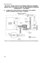
Figure 3--29. Installation of Left Main Manifold Pressure Transducer T7
Back to Top


