TB-9-2320-279-13-P-2 - Page 99 of 460
TB 9-2320-279-13&P-2
DOOR LATCH ADJUSTMENT - CONTINUED
0016 00
0016 00-3/(0016 00-4 Blank)
ADJUSTMENT - CONTINUED
NOTE
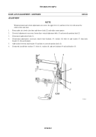
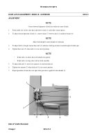
When link rod adjustment is correct, the latch lever (14) will be touching the actuating lever (15).
7.
If link rod (10) adjustment is necessary, remove locknut (13), washer (12), and bolt (11) from end of link rod. Discard
locknut.
8.
Rotate link rod (10) counterclockwise to bring latch lever (14) down.
9.
Rotate link rod (10) clockwise to bring latch lever (14) up.
10.
Align link rod (10) with hole in latch lever (14) and install bolt (11), washer (12) and new locknut (13) in end of link rod
(10).
NOTE
Slight downward pressure on door handle should release latch and open door.
11.
Repeat procedure if door does not open when slight downward pressure is applied to handle.
END OF WORK PACKAGE
417-031
10
11,12,13
14
15 (HIDDEN)
2
Back to Top


