TB-9-2350-277-40-P-2 - Page 25 of 100
TB 9-2350-277-40&P-2
REMOVAL PROCEDURES
0003 00
0003 00-1
THIS WORK PACKAGE COVERS:
Remove Power Plant Upper Rear Access Panel (page 0003 00-1).
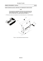
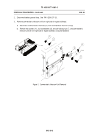
Remove Engine Bulkhead Hardware or Commander’s Intercom Unit (page 0003 00-2).
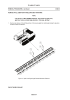
Remove Spall Liner Right Angle Bracket Hardware (page 0003 00-4).
INITIAL SETUP:
Maintenance Level
Sustainment
Tools and Special Tools
General Mechanic’s Tool Kit (WP 0012 00, Item 5)
Personnel Required
Mechanic
References
TM 9-2350-277-20
Equipment Conditions
Carrier parked on level ground
Engine stopped (TM 9-2350-277-10)
Vehicle blocked (TM 9-2350-277-10)
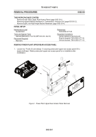
REMOVE POWER PLANT UPPER REAR ACCESS PANEL
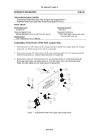
1.
Loosen four T-bolts (2) and clamps (1) securing power plant upper rear access panel (3) to
engine bulkhead.
Retain power plant upper rear access panel for re-installation after
modification.
Figure 1.
Power Plant Upper Rear Access Panel Removal
Back to Top

