TB-9-2350-277-40-P-4 - Page 25 of 100
TB 9-2350-277-40&P-4
REMOVAL PROCEDURES
0003 00
0003 00-1
THIS WORK PACKAGE COVERS:
Remove Intercom Unit (M1068A3 Only) (page 0003 00-1).
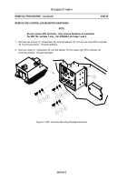
Remove APU Controller Mounting Hardware (page 0003 00-2).
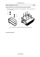
Remove Extension Cover Tent Angle Bracket Mounting Hardware (page 0003 00-3).
INITIAL SETUP:
Maintenance Level
Sustainment
Tools and Special Tools
General Mechanic’s Tool Kit (WP 0011 00, Item 5)
Personnel Required
Mechanic
References
TM 9-2350-277-20
Equipment Conditions
Carrier parked on level ground
Engine stopped (TM 9-2350-277-10)
Vehicle blocked (TM 9-2350-277-10)
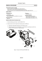
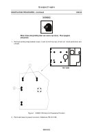
REMOVE INTERCOM UNIT (M1068A3 ONLY)
1.
Disconnect battery ground strap.
See TM 9-2350-277-20.
2.
Remove intercom unit from right side of auxiliary power unit (APU) (6).
a.
Disconnect communication harness (3) from intercom unit (5).
b.
Remove two screws (4), four lockwashers (1), two locknuts (2), and intercom unit (5) from
right side of APU controller (6).
Discard hardware.
Figure 1. Intercom Unit Removal (M1068A3 Only)
Back to Top

