TB-9-2350-277-40-P-4 - Page 26 of 100
TB 9-2350-277-40&P-4
REMOVAL PROCEDURES – Continued
0003 00
0003 00-2
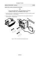
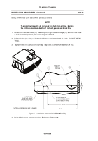
REMOVE APU CONTROLLER MOUNTING HARDWARE
NOTE
Do not remove APU controller.
Only remove hardware as instructed.
For M577A3, do Step 1 only.
For M1068A3, do Steps 1 and 2.
1.
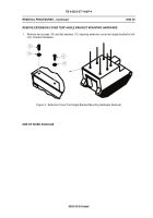
Remove two screws (7), lockwashers (8), and flat washers (9) from the two lower APU controller
(6) mounting positions.
Discard hardware.
2.
Remove screw (7), lockwasher (8), and flat washer (9) from upper right APU controller (6)
mounting position.
Discard hardware.
Figure 2.
APU Controller Mounting Hardware Removal
Back to Top

