TB-9-2350-277-40-P-4 - Page 33 of 100
TB 9-2350-277-40&P-4
MODIFICATION PROCEDURES – Continued
0004 00
0004 00-5
DRILL CREW II PRIMARY UNIT ENCLOSURE MOUNTING
NOTE
To protect hull integrity, do not break thru hull when drilling.
Marking
the drill for a maximum depth of 1-1/4 inches will prevent any break
thru.
1.
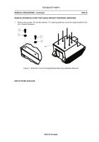
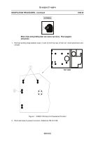
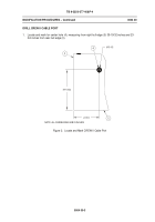
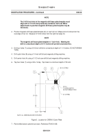
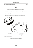
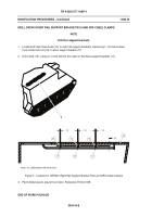
Locate and mark four holes (9), measuring from right hull edge (5) and from rear hull edge (3).
2.
Drill four holes (9) using a 27/64 inch drill bit to a maximum depth of 1-1/4 inches.
DO NOT
BREAK THRU.
3.
Tap four holes (9) using a 1/2 x 13 tap.
Tap holes to a minimum depth of 1-1/8 inch.
Figure 4.
Location for CREW II Primary Unit Enclosure Mounting Bracket
4.
Paint drilled area to prevent corrosion. Reference TM 43-0139.
Back to Top

