TM-10-5411-205-13 - Page 32 of 127
TM 10-5411-205-13
3-9.
General Repair Procedures (cont).
(2)
(b)
(c)
(d)
(e)
(f)
(g)
(h)
(i)
(j)
Drill hole in structure.
Remove all metal chips and remove burrs from drilled holes.
If flush head rivet is being installed, countersink hole using a 100-degree
or 120-degree machine countersink.
Coat all rivet bodies with sealer (Item 28, Appendix D) before installing.
Insert rivet in hole. Make sure sheets are held tightly together before
upsetting or pulling rivet.
Select proper pulling head for rivet being installed and install pulling head
on rivet gun.
Insert stem of rivet into pulling head.
With pulling head parallel to axis of rivet, upset rivet. Exert firm pres-
sure but do not bend or buckle metal sheets. Stem will break off below
rivet head surface. No trimming should be required.
Make sure riveted parts are not loose, rivet does not rotate, and rivet head
is seated tightly against riveted surface. If rivet is loose or improperly
installed, remove it and install a new one.
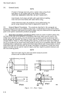
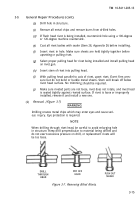
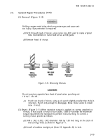
Removal. (Figure 3-7)
WARNING
Drilling creates metal chips which may enter eyes and cause seri-
ous injury. Eye protection is required.
NOTE
When drilling through rivet head, be careful to avoid enlarging hole
in structure. Keep drill perpendicular to material being drilled and
do not exert excessive pressure on drill, or replacement rivets will
be too loose.
DRILL
PRY OFF
THROUGH
HEAD
HEAD
PUSH OUT
SHANK
Figure 3-7. Removing Blind Rivets,
3-15
Back to Top

