TM-10-5411-205-13 - Page 30 of 127
TM 10-5411-205-13
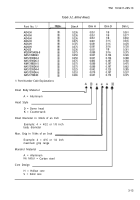
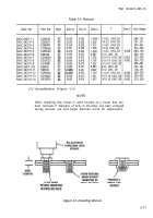
Table 3-2. Blind Rivets.
Part No. 1/
AD42H
AD43H
AD45H
AD62H
AD64H
AD68H
AD42S
MS20470AD6-8
NAS1398D43
NAS1398D4-4
NAS1398D6-3
NM1398D6-5
NAS1398D6-8
NAS1399D4-4
NAS1399D6-6
NAS1739E43
1/ Part Number Code Explanations
Rivet Body
A =
Head Style
D =
K =
Material
Dim A
0.236
0.236
0.236
0.375
0.375
0.375
0.236
0.375
0.250
0.250
0.375
0.375
0.375
0.225
0.353
0.286
Aluminum
Dim H
0.051
0.051
0.051
0.081
0.081
0.081
0.051
0.080
0.067
0.067
0.080
0.080
0.080
0.042
0.070
0.047
Dome head
Countersunk
Rivet Diameter in 32nds of an Inch
Example: 4 = 4/32 or 1/8 inch
body diameter
Max. Grip in 16ths of an Inch
Dim D
1/8
1/8
1/8
3/16
3/16
3/16
1/8
3/16
0.156
0.156
0.187
0.187
0.187
0.125
0.187
0.173
Mandrel Material
Example: 4 = 4/16 or 1/4 inch
maximum grip range
A = Aluminum
No letter = Carbon steel
Core Design
H = Hollow core
S = Solid core
Dim L
0.361
0.377
0.502
0.345
0.470
0.720
0.361
0.375
0.326
0.388
0.350
0.475
0.662
0.385
0.537
0.375
3-13
Back to Top

