TM-10-5411-205-13 - Page 36 of 127
TM 10-5411-205-13
3-9.
General Repair Procedures
(2)
Removal
(Figure 3-10)
(cont).
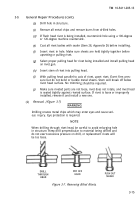
WARNING
Drilling creates metal chips which may enter eyes and cause seri-
ous injury. Eye protection is required.
(a)
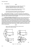
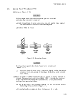
Drill through head of rivnut, using same size drill used to make original
hole. Counterbore in rivnut will act as a drill guide.
(b)
Remove head of rivnut.
Figure 3-10. Removing Rivnuts.
CAUTION
Do not puncture opposite face sheet of panel when punching out
rivnut shank.
(c)
Punch out shank of rivnut, using a pin punch slightly smaller than hole in
structure. Punch only enough to disengage. Move rivnut aside to install
new rivnut.
(3)
Repair.
(Figure 3-11) When excessive torque is applied on screws attached on
rivnuts, it may cause a rivnut to turn (spin). Table 3-4 provide the maximum
torque requirement for hardware to prevent rivnut turning. To correct a
turning rivnut, proceed as follows:
(a)
Drill a .062 (+.003, -.001) diameter hole by 1.00 inch long on the stem of
the turning rivnut as shown in Figure 3-11.
(b)
Install a headless straight pin (Item 25, Appendix D) in hole.
3-19
Back to Top

