TM-5-2350-377-13-P - Page 141 of 404
FIELD MAINTENANCE
CONTROL BOX WIRING HARNESS REPLACEMENT
INITIAL SETUP:
Tools and Special Tools
Tool Kit, General Mechanic's: Automotive
(WP
0071, Table 1, Item 7)
Shop Equipment, Field Basic
(WP
0071, Table 1, Item 5)
Personnel Required
Construction Equipment Repairer, 91L
References
TB 43-0001-39 Series
Equipment Condition
Front of vehicle blocked (TM 5-2350-262-20)
Hydraulic system pressure relieved
(TM
5-2350-262-20)
REMOVAL
NOTE
Refer to TB 43-0001-39 Series for all wiring harnesses not shown for Replacement task.
1.
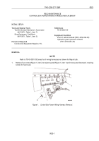
Remove four screws (Figure 1, Item 1) and cover (Figure 1, Item 2) from body assembly (Figure 1, Item 9) and
retain for future use.
2.
Disconnect connector (Figure 1, Item 4) on control box harness (Figure 1, Item 5) from connector
(Figure
1,
Item 7) on control box harness (Figure 1, Item 8).
3.
Remove control box harness connector (Figure 1, Item 6) and control box connector (Figure 1, Item 10) from
control box assembly (Figure 1, Item 9).
4.
Remove ten screws (Figure 1, Item 3) and control box harness contacts (Figure 1, Item 5) from cover
(Figure
1, Item 2) and retain screws for future use.
1
M0105HBF
2
2
3
4
6
7
5
10
9
8
Figure 1.
Control Box Harnesses Removal.
END OF TASK
TM 5-2350-377-13&P
0027
0027-1
Back to Top


