TM-5-3805-264-13-P - Page 244 of 660
INSTALLATION - Continued
8.
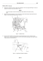
Working from underside of vehicle, release lower half (Figure 7, Item 3) and upper half (Figure 7, Item 2) of
stabilizer from bottom of dump body (Figure 7, Item 1).
NOTE
It may be necessary to raise front of dump body to align stabilizer with chassis mounting
holes.
9.
Raise front of dump body (Figure 7, Item 1) and position wooden blocks between dump body frame rails
(Figure 7, Item 5) and vehicle chassis (Figure 7, Item 4).
Figure 7.
Stabilizer Down.
10.
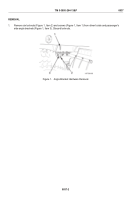
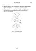
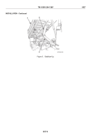
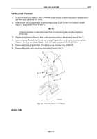
Align lower half of stabilizer mounting surface to angle brackets (Figure 8, Item 3). Install six screws
(Figure 8, Item 1) and new locknuts (Figure 8, Item 2) in driver's side and passenger's side angle brackets.
Torque locknuts to 150 lb-ft (203 N•m).
Figure 8.
Angle Bracket Hardware Installation.
TM 5-3805-264-13&P
0037
0037-10
Back to Top

