TM-5-3805-264-13-P - Page 245 of 660
INSTALLATION - Continued
11.
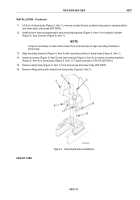
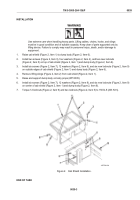
Lift front of dump body (Figure 9, Item 1), remove wooden blocks, position body props in raised position,
and lower body onto props (WP 0005).
12.
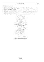
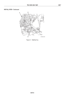
Install driver's side and passenger's side mounting brackets (Figure 9, Item 4) on hydraulic cylinder
(Figure 9, Item 2) pivots (Figure 9, Item 7).
NOTE
It may be necessary to raise and/or lower front of dump body to align mounting brackets to
dump body.
13.
Align mounting brackets (Figure 9, Item 4) with mounting surface of dump body (Figure 9, Item 1).
14.
Install six screws (Figure 9, Item 5) and new locknuts (Figure 9, Item 3) to secure mounting brackets
(Figure 9, Item 4) to dump body (Figure 9, Item 1). Torque locknuts to 150 lb-ft (203 N•m).
15.
Remove dump body (Figure 9, Item 1) from body props and lower body (WP 0005).
16.
Remove lifting device with chains from dump body (Figure 9, Item 1).
Figure 9.
Mounting Bracket Installation.
END OF TASK
TM 5-3805-264-13&P
0037
0037-11
Back to Top

