TM-5-3895-372-20 - Page 32 of 694
TM 5-3895372-20
Section VIII HYDRAULIC SYSTEM
2-17. INTRODUCTION.
The hydraulic system is driven by belts from the main drive (Section II) and provides power for the mixer-auger
(Section VII).
2-18. DESCRIPTION.
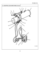
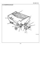
1.
OIL FILTER.
Removes impurities from oil entering pump.
Throw-away 33 micron paper element.
2.
RELIEF VALVE.
Adjusted to control pressure in hydraulic system.
When pressure rises above 1900-2000
psi (1310013800 kPa), diverts oil to reservoir instead of control valve.
3.
FILLER CAP.
Has dipstick for checking reservoir oil level.
4.
BREATHER.
Allows air and fumes from hot oil to escape.
5.
RETURN LINE.
Carries oil back to reservoir from control and bypass valves, relief valve, and motor.
6.
BYPASS VALVE.
(Normally closed).
Used to slow mixer-auger during cleanup.
When open, allows some
oil from motor supply line to escape to reservoir.
Color coded bands on stem aid in establishing proper rate
of bypass.
7.
HYDRAULIC MOTOR.
Turns mixer-auger.
Driven by oil under pressure from pump.
8.
CONTROL VALVE.
When lever is pushed forward, oil is blocked from motor and returns to reservoir
through return line.
When lever is pulled back, return line is blocked.
Oil goes to motor and mixer-auger
operates.
9.
HYDRAULIC RESERVOIR.
Holds reserve supply of oil for system.
34 gal (129 liter) capacity.
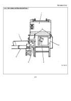
10.
DRAIN PLUG.
Used to drain reservoir.
11.
TACHOMETER.
Indicates hydraulic pump speed.
Normal range is 1620-1720 rpm.
Driven by cable from
center of hydraulic pump pulley.
12.
HYDRAULIC PUMP.
Supplies pressure to drive hydraulic motor.
Driven by six V-belts from main drive.
Pump speed depends on truck engine speed.
Will vary as main clutch and mixer-auger are engaged.
13.
GAGE POINT.
(Normally plugged).
Plug can be removed and gage inserted to test hydraulic pressure.
Pressure should be 1900-2000 psi (13100-13800 kPa).
Located so gage can be read while relief valve is
adjusted.
2-18
Back to Top

