TM-5-3895-372-20 - Page 38 of 694
TM 5-3895-372-20
Section XI LAMPS
2-23
. INTRODUCTION.
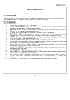
The lamps on the mixer body are an extension of the chassis marker and clearance lamps system. The lamps go
on automatically when the chassis blackout switch is set to NORMAL and the headlamp switch is in either of its
two "ON" positions.
(See TM 9-2320-273-20 for a description of chassis marker arid clearance lamps).
2-24. DESCRIPTION.
1.
MARKER LAMPS. Five red lamps across the back of the cement bin and one on each side of the bin.
Mark the rear of the mixer body.
Wired from inside the cement bin.
2.
CLEARANCE LAMPS.
Four yellow lamps on the upper front corners of the aggregate bins. Two face
forward, one faces to each side.
Mark width of mixer body.
3.
12-VOLT CONNECTOR.
Supplies power for the mixer body lamps from the chassis marker and clearance
lamp circuit.
4.
YELLOW REFLECTOR.
Two, one located at front of mixer body on each side. Reflect light to other
vehicle(s) for visual safety, if lamps are not functioning.
5.
RED REFLECTOR.
Two, one located at rear of mixer body on each side.
Reflect light to other vehicle(s)
for visual safety, if lamps are not functioning.
2-24
Back to Top


