TM-5-3895-372-20 - Page 36 of 694
TM 5-3895-372-20
Section X ELECTRIC WINCH
2-21. INTRODUCTION.
The electric winch raises and lowers the mixing trough.
It draws power from the chassis electrical system.
2-22. DESCRIPTION.
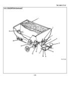
1.
WINCH CABLE.
Raises, lowers, and supports mixing trough.
2.
PULLEYS (4).
Guide winch cable.
Three on body, one on trough.
3.
CABLE END.
Anchored to loop on trough support frame.
4.
LIMIT SWITCH.
Normally closed.
Opened by bar on trough when trough is pulled up against the support
frame.
Breaks circuit between RAISE button and IN solenoid.
5.
CABLE REEL.
Pays out and winds in cable.
Chain driven by winch motor.
6.
IN SOLENOID.
Activated by signal from RAISE button through limit switch or JOG switch.
Causes cable to
be sealed in.
7.
JOG BUTTON.
When pressed at the same time as RAISE button, completes circuit to IN solenoid.
Provides alternative pathway to raise trough slightly after limit switch opens.
8.
RAISE BUTTON.
When pressed, partially closes circuit to IN solenoid.
Circuit must be completed through
limit switch or JOG button.
9.
LOWER BUTTON.
When pressed, closes circuit to the OUT solenoid.
Used to lower trough.
10.
GROUND CABLE.
Grounds winch circuit to chassis frame.
11.
POWER UNIT CABLE.
Supplies winch with 12V power from starter solenoid of chassis electrical system.
(See TM 9-2320-273-20 for a description of the chassis electrical system.)
12.
OUT SOLENOID.
Activated by signal from LOWER button.
Causes cable to be paid out.
13.
WINCH MOTOR.
12-volt electrical motor turns cable reel.
Energized by IN and OUT solenoids.
14.
WINCH GUARD.
Sheet metal box covers winch motor, solenoids, and reel.
Bolted to rear of cement bin.
2-22
Back to Top


