TM-5-5420-202-20-2 - Page 703 of 734
TM 5-5420-202-20-2
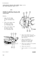
TURBOCHARGER SHROUDS REPLACEMENT (Sheet 2 of 5)
Inner Shroud Replacement (Sheet 2 of 3)
NOTE
Procedures for replacement of the left or right
transmission shrouds are similar. Procedures for the
left side are shown.
REMOVAL:
1.
Using 11/16 inch wrench,
disconnect hose assembly
(A) from turbocharger elbow
(B).
2.
Using 1/2 inch socket, remove
two screws and washers
(C) securing inner shroud
(D) to turbocharger plate.
3.
Using 1/2 inch socket, remove
two screws and washers
(E) securing inner shroud
(D) to turbocharger plate.
4.
5.
6.
8.
7.
Using 1/2 inch wrench and 1/2 inch
socket, remove screw, lockwasher, and
nut (F) securing inner shroud (D) to
upper shroud (G).
Using 1/2 inch socket and
extension, remove three screws
and washers (H) securing inner
shroud (D) to oil cooler frame.
Remove
(J) from
Remove
Remove
(A).
hose assembly (A) and grommet
inner shroud (D).
inner shroud (D).
grommet (J) from hose assembly
Go on to Sheet 3
9-42
Back to Top


