TM-9-1240-401-34-P - Page 330 of 590
TM 9-1240-401-34&P
7-10. LINKAGE ASSEMBLY MAINTENANCE INSTRUCTIONS - continued
b. Repair
1 Remove corrosion, grease, and dirt from all parts.
Refer to TM 9-254 for cleaning instructions.
2 Visually inspect for missing or damaged parts.
3 Repair or replace parts in accordance with author-
ized parts listed in appendix D.
c. Assembly
1
2
3
4
5
6
7
8
9
10
11
12
13
14
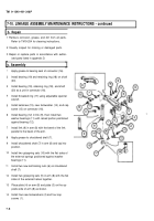
Apply grease to bearing seat of connector (16).
Install bearing (19) and retaining ring (18) on shaft
(20).
Install bearing (19), retaining ring (18), and shaft
(20) as a unit in connector (16).
Install threaded ring (17) using adjustable spanner
wrench.
Install setscrew (15), new Iockwasher (14), and cap
screw (13) on connector (16).
Install bearing (12) in link (9), then install two
washer bearings (11) with raised portion positioned
against bearing (12).
Install link (9) in arm (8) with the bevel of the link
parallel to the bevel of the arm.
Apply grease to shouldered shaft (7).
Install shouldered shaft (7) in arm (8) and tap into
position.
Install two gripspring sets (10) with the flat sides of
the external springs positioned against washer
bearings (11).
Install two new self-locking nuts (6) on shouldered
shaft (7).
Install two gripspring sets (5) in arm (8) with the flat
sides of the external halves together.
Place plate (4) on arm (8) and plate (3) on the op-
posite side of arm (8) as shown.
Install four new Iockwashers (2) and four cap
screws (1).
7-6
Back to Top


