TM-9-1240-401-34-P - Page 321 of 590
6-11
TM 9-1240-401-34&P
I
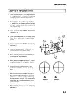
b. INSTALLING M42 PERISCOPE ON INSPECTION FIXTURE
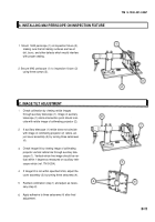
1 Mount M42 periscope (1) on inspection fixture (2),
making sure that all mating surfaces are free of
dirt, burrs, and other defects which would interfere
with proper seating.
2 Secure M42 periscope (1) to inspection fixture (2)
using three screws (3).
I
C. IMAGE TILT ADJUSTMENT
1
2
3
4
5
6
Check collimation by viewing reticle images
through auxiliary telescope (1). Image of auxiliary
telescope (1) reticle intersection point should coin-
cide with reticle image of collimating projector (2).
If auxiliary telescope (1) reticle does not coincide
with image of collimating projector (2) reticle, ad-
just cover assembly (3) by turning three setscrews
(4).
Check image tilt by viewing image of collimating
projector vertical reticle line through auxiliary tele-
scope (1). Vertical reticle line image should be ver-
tical within 1 degree as measured on auxiliary tele-
scope reticle (ref. TM 9-254).
If image tilt is not within specified limits, adjust the
cover assembly (3) by turning three setscrews (4).
Recheck collimation (step 1) and adjust as neces-
sary (step 2).
Apply adhesive to three setscrews (4) after final
adjustment.
Back to Top


