TM-9-1240-401-34-P - Page 327 of 590
7-3
TM 9-1240-401-34&P
7-6. INITIAL
INSPECTION
Item No.
Item To Be Inspected
Procedures
1
LINKAGE ASSEMBLY
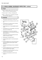
Check that all components are properly positioned and
securely attached.
Check that linkage assembly (1) operates smoothly without
binding or sticking.
2
CONNECTOR SHAFT
Check that both sides of connector shaft (2) are free of rust,
corrosion, and burrs.
3,4
BEARINGS AND SHAFTS
Check that bearings (3) and shafts (2 and 4) are not
worn, as indicated by lateral movement of link (5).
Section Ill. Troubleshooting
7-7. GENERAL
a.
The symptom index can be used as a quick guide to troubleshooting. Common malfunctions are listed in alpha-
betical order with a page number reference to the troubleshooting table, where a test or inspection and corrective
action are provided.
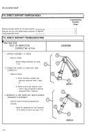
b. The direct support troubleshooting table (ref. para 7– 9) lists the common malfunctions which maybe found dur-
ing maintenance of the linkage assembly. Perform the tests/inspections and corrective actions in the order listed.
c.
This manual cannot list all malfunctions that may occur, nor all tests or inspections and corrective actions. If a
malfunction is not listed, or is not corrected by listed corrective action, notify depot maintenance.
Back to Top


