TM-9-1240-401-34-P - Page 329 of 590
TM 9-1240-401-34&P.
Section IV. Direct Support Maintenance Procedures
7-10. LINKAGE ASSEMBLY MAINTENANCE INSTRUCTIONS
This task covers:
a. Disassembly b. Repair c. Assembly
INITIAL SET-UP
Tools
Lockwashers (4) (Item 79, appx E)
Self-locking
Tool Kit, Electronic System, Repair, Field Mainte-
nance (SC5180-95-CL-B29) 51 80–01-1 68-0487 References
TM 9-254
nuts (2) (Item 18, appx E)
Grease (Item 6, appx B)
Lockwasher (Item 78, appx E) for 8267877
Linkage assembly removed from howitzer
Lockwasher (Item 74, appx E) for 12563124
(TM 9-2350-311-20-2 /TM 9-2350-314-20-2)
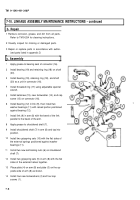
a. Disassembly
I
1
2
3
4
5
6
7
8
9
Remove four cap screws (1) and four Iockwashers
(2). Discard Iockwashers.
Remove
(5).
Remove
shaft (7).
plate (3), plate (4), and two gripspring sets
two self-locking nuts (6) from shouldered
Tap shouldered shaft (7) from arm (8)
with brass drift punch. Discard self-locking nuts.
Separate arm (8) from link (9) and remove two
gripspring sets (10).
Remove two washer bearings (11) and bearing
(12) from link (9).
Remove cap screw (13), Iockwasher (14), and
setscrew (15) from connector (16). Discard lock-
washer.
Using adjustable spanner wrench, remove
threaded ring (17).
Remove retaining ring (18), bearing (19), and shaft
(20) as a unit.
Remove retaining ring (18) and bearing (19) from
shaft (20).
7-5
Back to Top

