TM-9-2320-209-20-3-1 - Page 725 of 830
TM 9-2320-209-20-3-1
FRAME 2
1.
2.
3.
4.
5.
6.
7.
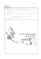
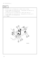
Push shifter shaft lever (1) toward rear of truck as far as it will move. This
is neutral position,
Place link assembly (2) as shown and check to see if ball joint studs (3) aline
with holes in shift control lever (4) and shifter shaft lever (1).
If ball joint studs (3) aline and seat firmly in holes,
screw on two locknuts (5).
Use one 5/8-inch wrench to hold two studs while tightening two locknuts with
3/4-inch wrench.
If ball joint studs (3) do not aline and seat firmly in holes, do steps 5, 6, and
7 to shorten or lengthen link assembly (2).
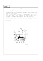
Using 3/4-inch wrenches, loosen two jamnuts (6).
Using vise grip pliers, turn link assembly (2) left or right as necessary until
ball joint studs (3) aline with holes.
Using 3/4-inch wrenches,
tighten two jamnuts (6) and do step 3 again.
END OF TASK
9-15
Back to Top


